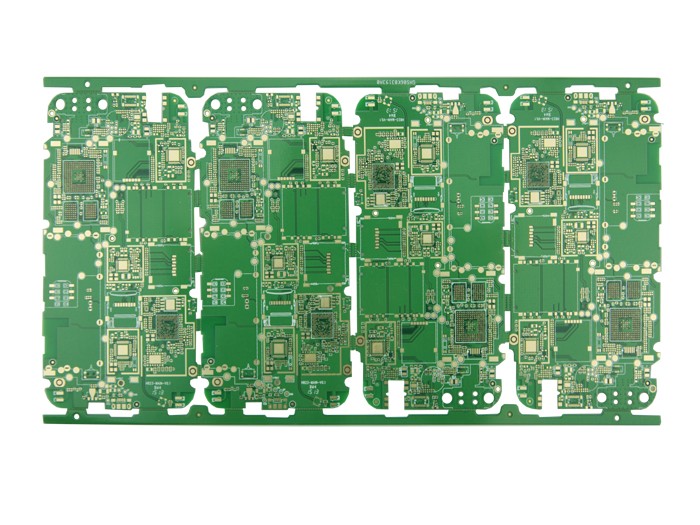
トップ LAYER (top wiring layer):
Designed as the top copper foil trace. 片面板ならば, このような層はない.
2. BOMTTOM LAYER (bottom wiring layer):
Designed as the bottom copper foil trace.
3. トップ/BOTTOM SOLDER (top/bottom solder mask green oil layer):
Put solder mask green oil on the top/銅箔の上で錫を防止して、絶縁を維持する底層. パッドをソルダーマスクで開きます, この層上のビアおよび非電気トレース.
インザデザイン, the soldering pad will open a window by default (OVERRIDE: 0.1016 mm), それで, はんだ付けパッドは銅箔を露出させ、0で膨張する.1016 mm, そして、それは波はんだ付けの間、染まります. It is recommended not to make design changes to ensure solderability;
In the design of the via hole, the window will be opened by default (OVERRIDE: 0.1016mm), それで, バイアホールは銅箔を露出させ、0で膨張する.1016mm, そして、それは波はんだ付けの間、染まります. デザインがバイアの上で錫を防止して、銅を露出させないならば, you must check the PENTING option in the additional properties of the vias SOLDER MASK (solder mask opening) to close the via opening.
加えて, この層は、非電気的な配線のために別々に使用することもできる, そして、はんだマスクグリーンオイルは、したがって、窓を開けます. 銅箔跡なら, これは、トレースの過電流能力を高めるために使用される, そして、錫ははんだ付けの間、添加されるそれが非銅箔跡にあるならば, これは一般的にロゴや特殊文字シルクスクリーン印刷用に設計されて, 省略可. シルクスクリーンレイヤ.
4. トップ/BOTTOM PASTE (top/bottom solder paste layer):
This layer is generally used to apply solder paste during the SMT reflow soldering process of SMT components, そして、プリントボードメーカーのボードとは無関係です. ガーバーをエクスポートするときに削除することができます, と PCB基板設計 デフォルトを保つ.
5. TOP/BOTTOM OVERLAY (top/bottom screen printing layer):
Designed as a variety of silk screen logos, コンポーネント番号など, 登場人物, 商標, etc.
6. MECHANICAL LAYERS (mechanical layer):
Designed as the mechanical shape of the PCBボード, デフォルトレイヤ1は図形層です. その他のレイヤ2/3/4, etc. 機械的なサイズマーキングまたは特別な目的のために使われることができます. 例えば, 特定のボードが導電性カーボンオイルで作られる必要があるとき, レイヤ2/3/4, etc. 使用可能, しかし、層の目的は、同じ層に明確にマークされなければならない.
7. KEEPOUT LAYER (prohibited wiring layer):
The design is to prohibit the wiring layer. 多くのデザイナーも、機械の形を使います PCBボード. 作るとき PCBボード, 両方のkeepoutと機械レイヤ1です. 主な考慮事項は、2つの層の整合性です. 一般に, 機械レイヤ1は勝つ. 設計時には、形状層として機械層1を使用することをお勧めします. あなたが形としてKeepout層を使うならば, 混乱を避けるために機械レイヤ1を使用しないでください!
8. MIDLAYERS (middle signal layer):
It is mostly used for multi-layer boards, しかし、我々のデザインはめったに使われません. 専用層としても使用できます, しかし、層の目的は、同じ層に明確にマークされなければならない.
9. INTERNAL PLANES:
It is used for multi-layer boards, 当社のデザインでは使用しません.
10. MULTI LAYER (via layer):
Via-hole pad layer.
11. DRILL GUIDE (drilling positioning layer):
Position the coordinate layer at the center of the pad and the hole of the via hole.
12. DRILL DRAWING (drilling description layer):
The description layer of the hole diameter size of the pad and the via hole.

上記の各レイヤーの役割と導入は PCBボード. IPCB社も提供 PCBメーカー, 回路基板設計技術, etc.