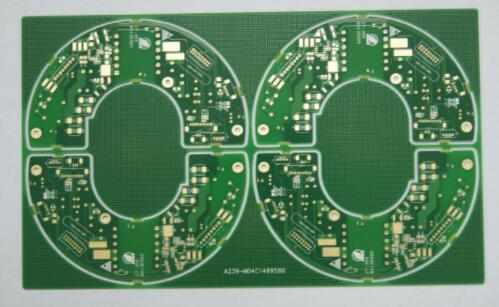
How to understand the circuit board wiring diagram? First of all, let's first understand the characteristics of the application circuit diagram:
1. Most of the application circuits do not draw the internal circuit block diagram, which is not good for the recognition of the diagram, especially for beginners to analyze the circuit work.
2. For beginners, it is more difficult to analyze the application circuits of integrated circuits than the circuits of discrete components. This is the reason for not understanding the internal circuits of integrated circuits. It is more convenient than discrete component circuits.
3. For integrated circuit application circuits, it is more convenient to recognize the diagram when you have a general understanding of the internal circuit of the integrated circuit and the function of each pin in detail. This is because the same type of integrated circuits have regularity. After mastering their commonalities, it is easy to analyze many integrated circuit application circuits with the same function and different types. The methods and precautions for the analysis of integrated circuit diagrams are mainly as follows:
(1) Understanding the function of each pin is the key to understanding the picture. To understand the function of each pin, you can refer to the relevant integrated circuit application manual. After knowing the function of each pin, it is convenient to analyze the working principle of the circuit outside each pin and the function of the components. For example: Knowing that pin 1. is an input pin, then the capacitor connected in series with pin 1. is the input coupling circuit, and the circuit connected to pin 1. is the input circuit.

(2) Three methods to understand the function of each pin of an integrated circuit There are three methods to understand the function of each pin of an integrated circuit: one is to consult relevant information; the other is to analyze the internal circuit block diagram of the integrated circuit; the third is to analyze the application circuit of the integrated circuit The circuit characteristics outside each pin are analyzed. The third method requires a good circuit analysis basis.
(3) Circuit analysis steps The circuit analysis steps for integrated circuit applications are as follows:
1. DC circuit analysis. This step is mainly to analyze the circuit outside the power supply and ground pins. Note: When there are multiple power supply pins, it is necessary to distinguish the relationship between these power supplies, such as whether it is the power supply pin of the previous and subsequent circuits, or the power supply pins of the left and right channels; for multiple grounding The pins should also be distinguished in this way. It is useful for repairing to distinguish multiple power pins and ground pins.
2. Analysis of signal transmission. This step mainly analyzes the signal input pin and the external circuit of the output pin. When the integrated circuit has multiple input and output pins, it is necessary to find out whether it is the output pin of the front stage or the back stage circuit; for the dual-channel circuit, it is also necessary to distinguish the input and output pins of the left and right channels.
3. Analysis of circuits outside other pins. For example, to find out the negative feedback pins, vibration damping pins, etc., the analysis of this step is the most difficult. For beginners, it is necessary to rely on the pin function data or the internal circuit block diagram.
4. After having a certain ability of recognizing pictures, learn to summarize the circuit rules outside the pins of various functional integrated circuits, and master this rule, which is useful for improving the speed of recognizing pictures. For example, the rule of the external circuit of the input pin is: connect to the output terminal of the previous circuit through a coupling capacitor or a PCB circuit board; the rule of the external circuit of the output pin is: connect to the input terminal of the subsequent circuit through a coupling circuit.

5. When analyzing the signal amplification and processing process of the internal circuit board of the integrated circuit, it is best to consult the internal circuit block diagram of the integrated circuit. When analyzing the internal circuit block diagram, you can use the arrow indication in the signal transmission line to know which circuit the signal has been amplified or processed, and the final signal is output from which pin.
6. Knowing some key test points and pin DC voltage rules of integrated circuits is very useful for circuit maintenance. The DC voltage at the output of the OTL circuit is equal to half of the DC operating voltage of the integrated circuit; the DC voltage at the output of the OCL circuit is equal to 0V; the DC voltages at the two output ends of the BTL circuit are equal, and it is equal to half of the DC operating voltage when powered by a single power supply. Hour is equal to 0V. When a resistor is connected between two pins of an integrated circuit, the resistor will affect the DC voltage on these two pins; when a coil is connected between the two pins, the DC voltage of the two pins is equal. When it is not equal, the coil must be open; when a capacitor is connected between two pins or an RC series circuit, the DC voltages of the two pins are definitely not equal. If they are equal, the capacitor has broken down.
7. Under normal circumstances, do not analyze the working principle of the internal circuit of the integrated circuit, which is quite complicated.