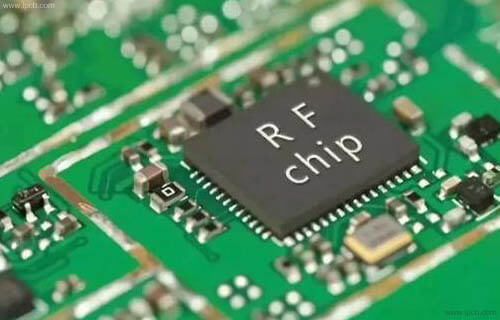
High frequency PCB is a radio circuit,but it does not involve microwave circuit (microwave is used to process circuits above 1000 MHz, starting from the electromagnetic field of physics, which is quite different from our common circuits), and is used for radio wave transmission, reception, modulation, demodulation, amplification, etc.
High frequency pcb(HF PCB) is a special circuit board with high electromagnetic frequency,used in the field of high frequency (frequency greater than 300MHZ or wavelength less than 1 metre) and microwave (frequency greater than 3GHZ or wavelength less than 0.1 metre) PCBs,which are produced by using part of the processes of the ordinary rigid circuit board manufacturing method or by using a special treatment method on a copper-clad board with a microwave substrate. In general, high-frequency boards can be defined as circuit boards with frequencies above 1GHz.
Plate characteristics for high frequency pcb(HF PCB):
1.DK should be small and stable enough,usually the smaller the better,high DK may lead to signal transmission delay.
2.DF should be very small,this mainly affects the quality of signal transmission,smaller DF can reduce the signal loss accordingly.
3.The coefficient of thermal expansion should be the same as that of the copper foil as far as possible,as the difference can cause the copper foil to separate during hot and cold changes.
4.Water absorption must be low in humid environments,high water absorption will affect DK and DF.
5.Heat resistance, chemical resistance, impact resistance,and peel resistance must be good.

high frequency PCB
Performance index of high frequency PCB
High frequency small signal amplifier has two kinds of circuit forms: resonant amplifier and broadband amplifier.The performance index mainly includes the following items.
1.Gain
High frequency circuit and low frequency circuit have voltage gain and power gain index. For the resonant amplifier circuit,it refers to the resonant frequency f0, for the broadband amplifier circuit, it refers to a frequency bubble.
2.Passband
Similar to the concept of low-frequency circuit, for resonant amplifier circuit, passband refers to the difference between two corresponding frequencies when the normalized amplitude drops to 0.707 relative to resonant frequency f0; for broadband amplifier circuit, it is the corresponding definition relative to a certain frequency.
3.Selectivity
Selectivity is mainly aimed at resonant amplifier circuit,which characterizes the circuit's ability to select useful signals to suppress useless signals.It is usually measured by rectangular coefficient and suppression ratio,which are based on the resonance characteristic curve of the circuit.
4.Noise figure
When the amplifier circuit works,due to various reasons,the carrier will move irregularly and form noise inside the circuit,which will affect the signal quality.This effect is usually described by the ratio of signal power PS to noise power PN (SNR).Noise figure is defined as the ratio of input signal to noise ratio and output signal to noise ratio.
5.Stability
The stability of high frequency amplifier circuit refers to the stability of its main performance when the working state or condition changes.For example,the change of the ambient temperature or the fluctuation of the power supply voltage will affect the DC working state of the amplifier circuit,the circuit component parameters will also change,which will cause the gain of the amplifier circuit to change,the center frequency offset,and the resonance curve distortion.Even self-excited and unable to work at all.

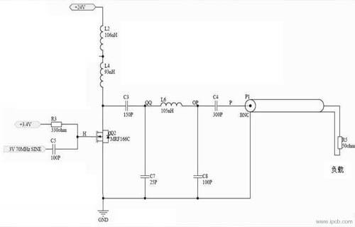
Schematic diagram of high frequency circuit
Introduction of RF PCB
Radio frequency is referred to as RF, radio frequency is the radio frequency current,it is a kind of high frequency alternating current electromagnetic wave abbreviation. Alternating current that changes less than 1000 times per second is called low-frequency current, and that greater than 1000 times is called high-frequency current,and radio frequency is such a high-frequency current.Cable television system is the use of radio frequency transmission
In the theory of electronics, when the current flows through the conductor, the magnetic field will be formed around the conductor when the alternating current passes through the conductor, the alternating electromagnetic field will be formed around the conductor, which is called electromagnetic wave.
When the frequency of electromagnetic wave is lower than 100kHz, the electromagnetic wave will be absorbed by the earth's surface, and can not form effective transmission.However, when the frequency of electromagnetic wave is higher than 100kHz, electromagnetic wave can spread in the air and reflect through the ionosphere at the outer edge of the atmosphere to form a long-distance transmission ability.We call the high-frequency electromagnetic wave with long-distance transmission capability as radio frequency.
Composition and characteristics of RF circuit
The RF circuit of ordinary mobile phone is composed of receiving channel,transmitting channel and lo circuit.It is mainly responsible for receiving signal demodulation and transmitting information modulation.The early mobile phones demodulate the received baseband information only after the superheterodyne frequency conversion (mobile phones have,two-stage mixing and one and two local oscillator circuits);the new mobile phones directly demodulate the received baseband information (zero if). In some mobile phones, the frequency synthesizer and receiver voltage controlled oscillator (rx-vco) are also integrated in the intermediate frequency.

What is the difference between high frequency PCB and RF PCB
Material Selection:
HF PCB typically uses materials with low dielectric constants (DK) and low dielectric loss factors (DF), such as polytetrafluoroethylene (PTFE) or special ceramic-filled resins,to minimise energy loss and delay of signals during transmission.
RF PCBs, on the other hand,are more concerned with the stability and variation of the dielectric constant,as well as the thickness of the material dielectric,the temperature drift coefficient and the strobe performance. Commonly used materials include polyphenylene ether (PPO or PPE), etc.
Design requirements:
The design of high frequency PCBs requires impedance control to ensure stability and integrity of signal transmission.This includes fine line width, spacing, and via size control.
In addition to precise impedance control,RF PCBs also require the integration of multiple RF components (e.g.,filters,amplifiers,mixers,etc.) and fine layout and wiring to ensure impedance matching and signal transmission performance of the interconnections between these components.
Application Scenario:
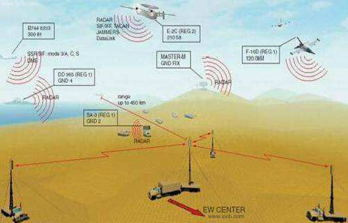
High frequency PCBs are widely used in high speed digital communication equipment,radar systems,satellite navigation equipment and so on.
RF PCBs, on the other hand, are widely used in wireless communication equipment (e.g. mobile phones,base stations),satellite communications, radar, radio frequency identification (RFID) systems and other fields.
The main differences between High frequency PCB and RF PCBs are their frequency requirements,material selection,design complexity and application scenarios.HF PCB is more inclined to general high-frequency signal applications,while RF PCB plays an important role in complex wireless signal processing.