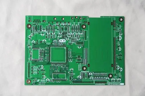
перед началом макета, a complete and detailed description of the circuit is required, mainly including the following aspects:
1) Schematic diagram, including details of компонент, соединение, and edge connector нормаs.
2) The component list, including the name, specification, model and manufacturer of the component.
3) Mechanical specifications, including the size and shape of the board, монтажное отверстие, marking of the height-restricted area of components, & Расположение граничных соединений.
4) Printed circuit board specifications, односторонний, double-sided or multi-substrate, отверстие для прохода ленты или без гальванизации.
5) Pattern specifications, including the type and size of pads, ширина и расстояние проводов.
6) Electrical specifications, for example, размещение компонентов должно быть ограничено теплоотдачей, емкость или индуктивность, ground plane, критическая длина монтажа, etc.
7) Data manipulation.

First, склад готовых компонентов, Он описывает тип упаковки для каждого компонента, including the shape, подкладка, size, Положение паяльного диска. In the complete component list, тип упаковки для каждого компонента, the name and location of the component, Следует также отметить поверхность соединения на печатных платах. таблица соединений дает точное описание всех точек для соединения точек. The final detailed information list of the circuit board contains board information and x/Y - координаты угла плиты. правильность данных, особенно важна форма соединения. In many CAD systems, требовать от двух независимых операторов подготовить список соединений для одной и той же цепи. только после устранения различий между двумя формами связи, можно ли продолжить следующие шаги.
A schematic diagram provides a graphical representation of the functional flow and circuit. первый шаг при проектировании печатных плат с использованием системы CAD - это ввод схемы. A schematic system includes:
1) Electrical connection (network);
2) Connection point;
3) Integrated circuit symbol;
4) Symbols of discrete components, сопротивление типа, capacitors, транзистор, etc.;
5) Input/output connector;
6) Power and ground symbols;
7) Bus;
8) Non-connected symbols;
9) Reference name of components;
10) Text description.
Эти символы в схеме электрических принципов должны соответствовать международным стандартам.
When the electrical schematic diagram is acquired, Каждая открытая графика - это отдельное "окно управления проектом". If you need to process several graphics at the same time, Ты можешь открыть все, each of which has its own "project management window". "окно управления проектом" используется для сбора и организации всех ресурсов, необходимых для проекта. These resources include schematic folders, schematic events, component libraries, components, and output reports, such as material lists and network tables. The management of a project does not actually include all the resources, Но указывает только на различные документы, необходимые для проекта. Therefore, never delete or move files related to any project. If deleted, Эти файлы больше не будут найдены.
выше описание этапа проектирования печатной схемы. Ipcb также предоставляет Производители PCB and PCB manufacturing technology.