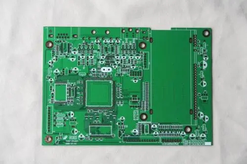
The design of the printed circuit board starts from determining the size of the board. размер печатных плат ограничен размерами корпуса картера. It is the connection method of potentiometer, socket or other printed circuit board). The printed circuit board and external components are generally connected by plastic wires or metal isolation wires. Но иногда она также проектируется как розетка. То есть: to install a plug-in printed circuit board in the device, сохранить контактное положение в качестве розетки. For larger components mounted on PCB printed circuit boards, metal accessories should be added to fix them to improve vibration and impact resistance.

2. The basic method of wiring diagram design
First of all, необходимость полного понимания норм, dimensions, площадь выбранного компонента и различных розеток; разумно и тщательно обдумывать расположение каждого компонента, mainly from the perspective of electromagnetic field compatibility and anti-interference. шлейф, less crossover, питание, ground path and decoupling are considered. определить расположение каждого элемента после, it is the connection of each component. связанный вывод по схеме. There are many ways to complete it. вспомогательное проектирование печатных схем осуществляется двумя способами: автоматизированным проектированием и ручным проектированием..
The most primitive is to arrange the layout by hand. Это труднее, and it often takes several iterations to complete it. Если нет других графических устройств, можно сделать это. This manual arrangement of layout methods is also very helpful for those who are just learning the printing plate layout. рисунок с помощью вычислительной машины, now there are many kinds of drawing software with different functions, но в целом, drawing and modification are more convenient, Они могут быть сохранены и распечатаны.
Next, установить размер требуемой печатной платы, принципиальная схема, initially determine the position of each component, затем непрерывно корректировать компоновку, чтобы сделать её более рациональной. The wiring arrangement between the components in the printed circuit board is as follows:
(1) Cross circuits are not allowed in printed circuits. для возможных переходов, you can use "drilling" and "winding" two methods to solve them. That is, let a lead "drill" through the gap under other resistors, конденсатор, and triode pins, или конец провода может пройти через "ветер". In special circumstances, Насколько сложна схема, it is also necessary to simplify the design. разрешить соединение проводов для решения проблемы скрещивания цепей.
(2) Components such as resistors, диод, and tubular capacitors can be installed in "vertical" and "horizontal" installation methods. вертикальная формула - установка и сварка блоков вертикальной плоскости, which has the advantage of saving space, горизонтальный - установка и сварка элементов параллельно и вблизи платы, and its advantage is that the mechanical strength of the component installation is better. для этих двух различных монтажных компонентов, the component hole pitch on the printed circuit board is different.
(3) The grounding point of the same level of circuit should be as close as possible, and the power filter capacitor of this level of circuit should also be connected to the grounding point of this level. особенно, the grounding points of the base and emitter of the transistor of this level cannot be too far apart, В противном случае медная фольга между двумя точками будет слишком длинной, which will cause interference and self-excitation. использование такой схемы с заземлением будет работать лучше. устойчивый и не поддающийся самовозбуждению.
(4) The main заземление must be arranged in strict accordance with the principle of high frequency-intermediate frequency-low frequency in the order of weak current to strong current. не может быть. The connection between the levels is rather long. соблюдать это требование. In particular, требование расположения заземления преобразователя, regeneration head, А головка с частотной модуляцией более строгая. If improperly, Он будет возбужден, чтобы не работать.. High-frequency circuits such as FM heads often use large-area surrounding ground wires to ensure a good shielding effect.
(5) Strong current leads (common ground, power amplifier power leads, сорт.) should be as wide as possible to reduce wiring resistance and voltage drop, уменьшение самовозбуждения в результате паразитной связи.
(6) The traces with high impedance should be as short as possible, канал записи с малым сопротивлением может быть длиннее, because the traces with high impedance are easy to whistle and absorb signals, Это может привести к дестабилизации цепи. The power cord, ground wire, base trace without feedback components, вывод эмиттера, etc. Это знак малого сопротивления. The base trace of the emitter follower and the ground traces of the two channels of the radio must be separated, Каждая полоса образует путь., Until the end of the function is combined again, Если два заземления соединяются, it is easy to produce crosstalk and reduce the degree of separation.
выше описаны основные принципы проектирования печатных схем. Ipcb is also provided to PCB manufacturers and PCB - производство technology.