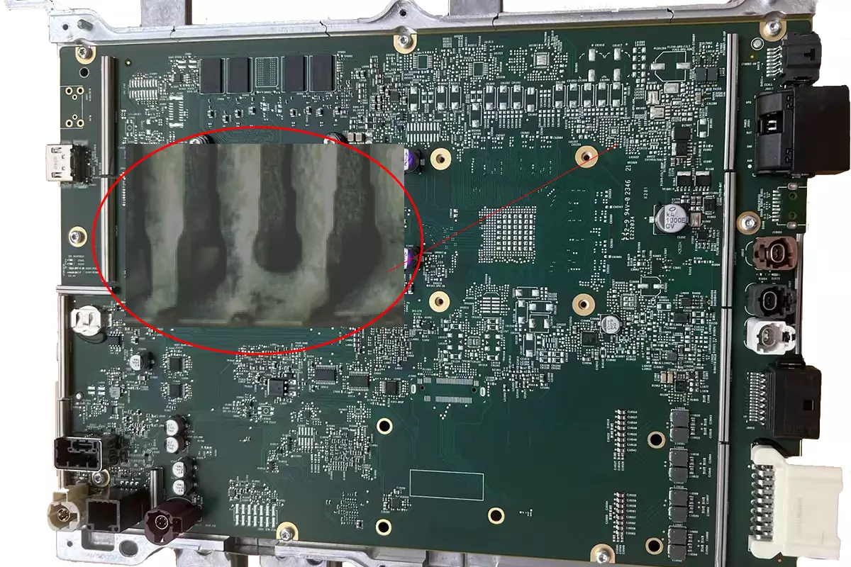
The volume requirements of electronic products are becoming smaller and smaller, and PCBA manufacturing also needs to pay close attention to tin-connection problems that are prone to occur during soldering. For example, a common defect in tin-connections is that the solder flows directly through the connector during high-temperature soldering, resulting in tin-connections. Tin connections may occur at different stages of the PCBA processing. So what is the reason for tin-connection? Is there any solution to avoid tin-connections?
Tin-connection is a conductive path formed by contact between solder pads. During the assembly process, problems that arise at different stages of the manufacturing process can lead to tin-connections. Tin-connection, also known as lap welding, refers to the unexpected connection between copper foils and solder joints that should not be connected during the soldering of printed circuit boards.
It should be noted that some of these defects are easy to identify, while others are difficult to determine by visual methods. For example, bridges connected by hair like fine solder can only be determined through electrical performance testing.
Tin connections often occur in circuit boards with high solder density during manual soldering, often due to trailing solder when the soldering iron tip is moved away. In addition, if too much solder is used, it will overflow the solder pads and cause accumulation near the solder joints, which can also cause defects in tin-connections. During the soldering process, the temperature is too high, causing adjacent solder joints to melt, and can also cause tin-connections in automatic soldering. The reasons for tin-connections in automatic soldering may be the speed of the conveyor belt and the temperature of the solder groove. In addition, impurities in the solder groove increase, the concentration of solder decreases, and the improper pulling angle when the printed circuit board leaves the solder surface can also cause tin-connections.
Tin-connection is a serious welding defect that causes two solder joints that should not have had electrical contact to become electrically connected, resulting in a short circuit between circuits. This can damage components and affect product performance, or even lead to personal accidents.

PCBA Tin-Connection
Reasons for Tin-Connection
1. Heavy components in the PCB board are placed on the same side, causing uneven weight distribution and tilting of the PCB.
2. The installation direction of the components is opposite.
3. The space between the gaskets lacks redundancy.
4. The temperature curve setting of the reflow soldering furnace is unreasonable.
5. The pressure setting of the patch is unreasonable.
Solution to causing tin-connection
1. PCB design: It is necessary to strictly carry out scientific planning at the circuit board design level, reasonably allocate the weight of components on both sides, reasonably distribute the opening of air vents and through holes, adjust the spacing of dense components, and add solder mask layers appropriately.
2. Reflow soldering furnace temperature curve: In PCBA manufacturing, literally speaking, when liquid solder melts, the higher temperature end of the solder has higher activity. If the reflow soldering temperature curve is not set properly, it will lead to disorderly flow of solder paste. Increase the probability of tin-connection.
3. Choosing a solder paste printing machine: A solder paste printing machine does not require the use of a steel mesh to apply solder paste, which will reduce poor solder paste contact coating caused by unreasonable template openings, steel mesh warping, and steel mesh detachment.
4. Reasonably control the amount of solder paste: Reasonably control the amount of solder paste applied to reduce the problem of excessive collapse and high fluidity of solder paste.
5. Reasonable setting of solder mask: Correctly setting the solder mask can greatly help reduce the risk of solder bridging
After understanding how to prevent tin-connection during soldering, you can focus on the process, PCB design, reflow curve, and other related issues when choosing a PCBA manufacturing factory, in order to reduce the uncontrollable PCBA cost expenditures caused by tin-connections.