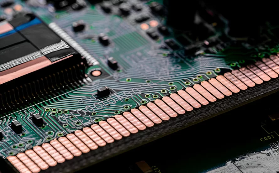
Printed circuit board edge connector, often referred to as gold finger connectors, feature gold-plated pads on the edge of a printed circuit board (PCB) designed to fit into specific sockets. These connectors are primarily used to connect the PCB to a motherboard or other peripheral storage devices. They are essential for high-speed and high-frequency signal applications, ensuring stable and reliable connectivity.PCB edge connectors are gold-plated contact fingers or pads that mate with corresponding connectors arranged along one or more edges of a circuit board. The board edge fits into a slot to make electrical contact.Edge connectors enable circuit boards to be easily installed, removed, and replaced from an electronic system.Gold is commonly used due to its durability and superior electrical conductivity. PCB edge connectors typically use either soft gold, such as Electroless Nickel Immersion Gold (ENIG), or hard gold plating. ENIG has a thickness range of 1U” to 3U”, whereas hard gold, which is more robust, ranges from 20U” to 50U".
Beveling printed circuit board edge connector, also known as chamfering, is crucial in designing PCB edge connectors. Standard bevel angles are typically 30 degrees, but angles of 20, 45, or 60 degrees may be used depending on connector specifications. The minimum edge thickness is 0.25 mm, and the thickness of the PCB edge connector can range from 1.6 mm to 2.4 mm. Chamfer tolerances range from 1% to 10%, following IPC standards.
Uniformly designed, equally spaced pads used in network equipment and graphic cards.Segmented Gold Fingers: Pads with small gaps, electrically separated for specific use cases,long and Short Gold Fingers: Varying pad lengths for devices like USB drives and memory cards.Cost-effective as they eliminate the need for manual connectors and wiring harnessesHigh durability, capable of withstanding over 1000 mating cycles without significant wear;compact designs improve overall product size while maintaining performance;gold-plated connectors offer excellent conductivity and corrosion resistance, ensuring long-lasting functionality.

printed circuit board edge connector
Applications of printed circuit board edge connector:PCB edge connectors are found in various industries, especially in telecommunications and computing, such as:Connecting USB or HDMI cables to laptops or PCs.Storage devices like SD cards and graphics cards in cameras.High-speed, high-precision applications in advanced industrial sectors.To ensure performance and durability, PCB edge connectors must follow strict design guidelines, such as:Minimum 0.5mm clearance between the connector edge and PCB board edge.Surface-mount devices and pads should be placed at least 2 mm away from the gold fingers.Copper removal is necessary in areas that expose internal layers during chamfering to avoid electrical issues.
Manufacturing Standards of printed circuit board edge connectorr:IPC standards provide clear guidelines for producing PCB edge connectors. They recommend a chemical composition of gold containing 3-15% cobalt for enhanced durability. Soft gold (1U” to 3U”) is generally used for prototypes, while hard gold (up to 50U”) is used for longer-term applications. Additionally, optical inspections and tape tests are employed to ensure the quality and reliability of the connectors.
Printed circuit board edge connector are the basic component units for electronic terminals to achieve signal transmission and exchange. A basic connector consists of four parts: contact interface, contact coating, contact elastic component and connector plastic body. Its function is to achieve the connection and separation between wires, cables, printed circuit boards and electronic components, and then transmit signals and exchange information. Different frequencies, powers and application environments will require different forms of connectors. Before deciding which connector to use, designers should consider the mechanical, electrical and environmental characteristics of the connector. If the designer is not familiar with the connector in the design of the project, it will have a great impact on the reliability of the project.If you have PCB Assembly needs, please contact iPCB.