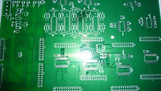
In PCB design,Suppressing the interference source is to reduce the du/dt and di/dt of the interference source as much as possible. This is the best consideration and the most important principle in anti-jamming design, and it often has the effect of getting twice the result with half the effort. Reducing the du/dt of the interference source is mainly achieved by connecting capacitors in parallel at both ends of the interference source. Reducing the di/dt of the interference source is achieved by connecting inductance or resistance in series with the interference source loop and adding a freewheeling diode.

in some PCB factory.Common measures to suppress interference sources are as follows:
(1) A freewheeling diode is added to the relay coil to eliminate the back-EMF interference generated when the coil is disconnected. Only adding a freewheeling diode will lag the off time of the relay. After adding a Zener diode, the relay can operate more times per unit time.
(2) Connect a spark suppression circuit in parallel at both ends of the relay contact (usually an RC series circuit, the resistance is generally selected from a few K to tens of K, and the capacitor is 0.01uF) to reduce the impact of electric sparks.
(3) Add a filter circuit to the motor, and pay attention to the shortest possible capacitor and inductance leads.
(4) Each IC on the PCB board should be connected with a 0.01μF~0.1μF high frequency p capacitor in parallel to reduce the IC's influence on the power supply. Pay attention to the wiring of high-frequency capacitors. The wiring should be close to the power supply terminal and as short as possible. Otherwise, the equivalent series resistance of the capacitor will be increased and the filtering effect will be affected.
(5) Avoid 90-degree fold lines when wiring to reduce high-frequency noise emission.
(6) The two ends of the thyristor are connected in parallel with an RC suppression circuit to reduce the noise generated by the thyristor (this noise may break down the thyristor).
According to the propagation path of interference, it can be divided into two types: conducted interference and radiated interference.
The so-called conducted interference refers to the interference that propagates to sensitive devices through wires. The frequency bands of high-frequency interference noise and useful signals are different. You can cut off the propagation of high-frequency interference noise by adding a filter on the wire, and sometimes you can add an isolation optocoupler to solve it. Power noise is the most harmful, so pay special attention to handling. The so-called radiated interference refers to the interference that propagates to sensitive devices through space radiation. The general solution is to increase the distance between the interference source and the sensitive device, isolate them with a ground wire and add a shield on the sensitive device.