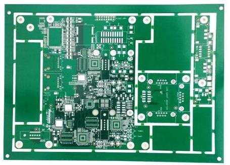
The common PCB plate medium used by PCB board manufacturer is FR4 material, and the dielectric constant of relative air is 4.2-4.7. This dielectric constant varies with temperature, and can vary as much as 20% over a temperature range of 0-70 degrees. The change of dielectric constant will result in a 10% change of the line delay on the PCB board. The higher the temperature, the greater the delay. The dielectric constant also varies with the signal frequency, and the higher the frequency, the smaller the dielectric constant. Under 100M, the capacitance and delay between plates can be calculated with 4.5.
In general, the internal signal transmission speed in the PCB board of FR4 material is 180ps/inch (1inch=1000mil=2.54cm). Surface layers generally vary from 140 to 170.
The capacitance on the actual PCB circuit board can be simply equivalent to L, R, C in series. The capacitance has a resonance point, which will show sensibility at high frequency (beyond this resonance point). The capacitance value and process of the capacitance on the PCB circuit board are different, and the production of different PCB board manufacturers will also be very different. This resonance point mainly depends on the equivalent series inductance. For example, the equivalent series inductance of the patch capacitance on a 100nF PCB board is about 0.5nH, the ESR (equivalent series resistance) value is 0.1 Euro, then it is filtered at around 24M and the AC impedance is 0.1 Euro. The equivalent inductance of a 1nF patch capacitance is also 0.5nH (the difference between different capacitance values is not great), ESR is 0.01 Euro, which can filter around 200M.

To achieve a good filter effect, we use capacitors of different capacitance values to match. However, due to the effect of equivalent series inductance and capacitance, there will be a resonance point between 24M and 200M, where there is a large impedance, which is greater than that of a single capacitor. That's the result we don't want. (In the range of 24M to 200M, the small capacitance of the PCB board is capacitive and the large capacitance is inductive.
The two capacitors on the PCB circuit board are already in parallel with LC. The sum of the ESR values of the two capacitors is the series resistance of this LC circuit. If the series resistance is 0 in parallel, then there will be an infinite impedance at the resonance point, which has poor filtering effect. This series resistance inversion suppresses this parallel resonance phenomenon and reduces the impedance of the LC resonator at the resonance point. To mitigate this effect, SMT SMT can use larger ESR capacitors here as appropriate. ESR is equivalent to the series resistance in the resonant network, which can reduce the Q value, thus flattening the frequency characteristics.