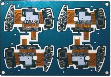
1. этот shape and size design standard of the pad in проектирование печатная плата
этот печатная плата standard package library should be called.
минимальная односторонняя сторона всех паяльных плит не менее 0.25mm, максимальный диаметр всей прокладки не более 3 раз.
Try to ensure that the distance between the edges of the two pads is greater than 0.4 мм.
In the case of dense wiring, рекомендуется использовать эллипсоидальные и прямоугольные соединительные доски. The diameter or minimum width of the single-sided board pad is 1.6mm панель слабой линии с двухсторонней панелью нужно только добавить 0.5mm to the hole diameter. паяльная тарелка слишком большая, чтобы вызвать ненужную непрерывную сварка.
прокладка с отверстием более 1 мм.2mm or pad diameter exceeding 3.0mm should be designed as diamond or quincunx pads
For plug-in components, in order to avoid the phenomenon of copper foil breaking during welding, and the single-sided connecting plate should be completely covered with copper foil; the minimum requirement for double-sided panels should be filled with teardrops; as shown in the figure:
All machine insert parts need to be designed as drip pads along the bent leg direction to ensure full solder joints at the bent leg.
прокладка на медной обшивке должна быть прокладкой хризантема, не свариваемый. If there is a large area of ground and power lines on the печатная плата ((площадь более 500 кв.мм)), the window should be partially opened or designed as a grid fill (FILL).

второй, печатная плата - производство process requirements for pads
Test points should be added to the two ends of the chip components that are not connected to the plug-in components. The diameter of the test point is equal to or greater than 1.8mm, легко тест.
If the IC pin pads with dense pin spacing are not connected to the hand-plug pads, нужно добавить тестовую прокладку. For SMD ICs, тестовая точка не может быть помещена в сеть SMD IC. The diameter of the test point is equal to or greater than 1.8mm, легко тест.
If the pad spacing is less than 0.4 мм, white oil must be applied to reduce continuous soldering when the wave crest is exceeded.
модуль SMD должен быть спроектирован как свинцовое олово. ширина свинца и олова рекомендуется использовать 0.5mm wire, длина обычно 2 или 3 мм.
если на одной панели есть ручная сварка, the tin bath should be removed, противоположная сторона от сварки, and the width of the hole is 0.3 мм на 1 мм.0MM; (50-70% of the hole diameter) as shown below:
The spacing and size of the conductive rubber buttons should be consistent with the actual size of the conductive rubber buttons. The печатная плата board connected to this should be designed as a gold finger, Соответствующая толщина золочения.
The size and spacing of the pad should be the same as the size of the chip component (1:1).
For the solder joints with the distance between the pads on the same straight line (the number of pads greater than 4) is less than 0.4mm, на основе добавляемого масла, the long side of the component is as parallel as possible to the direction of the wave crest, затем в конце добавить пустой паяльный диск или увеличить конец паяльной тарелки, Таким образом, уменьшать расход кормового припоя, уменьшать непрерывную сварка.