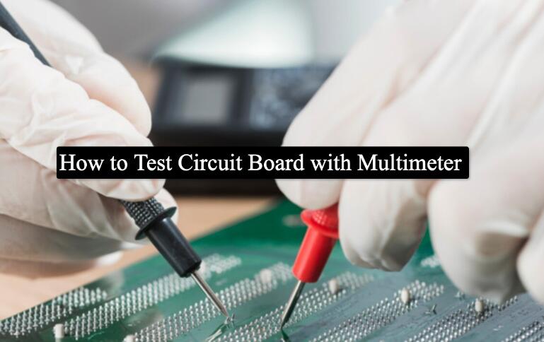
A multimeter is a multifunctional measuring instrument, typically designed to measure voltage, current, and resistance.How to test PCB board with multimeter?
1.Observation method
This method is quite intuitive, and through careful inspection, we can see the burn marks. When this problem occurs, we should pay attention to the rules during maintenance and inspection to ensure that there will be no more serious injuries when powered on.When using this method, we need to pay attention to the following issues:
1) Determine whether the PCB board has been artificially damaged by observation.
2) Carefully observe the components related to this circuit board, including each capacitor and resistor, to see if there is any blackening. Due to the inability to observe resistance, measurements can only be made using instruments. Relevant damaged parts should be replaced promptly.
3) Observation of integrated circuits on circuit boards, such as CPU, AD, and other related chips, and timely modification of bulges, burns, and other related situations should be made.
2.Static measurement method
When testing PCB board faults, it is often difficult to detect some problems through observation, unless they are burnt or deformed. However, most problems still require measurement with a voltmeter before conclusions can be drawn. Circuit board components and related parts should be tested one by one. The maintenance steps should be carried out according to the following process:
1) Detect the short circuit between the power supply and the ground, and investigate the cause.
2) Check if the diode is normal.
3) Check if there is a short circuit or even an open circuit in the capacitor. Step 4: Check the integrated circuits related to the circuit board, as well as the indicators of resistors and other related devices.
3.Online measurement method
1) Power on the circuit board and check if there is any overheating of the components. If there is, check and replace the relevant components.
2) Detect the gate circuit corresponding to the PCB board, observe if there are any issues with the logic, and determine the quality of the chip.
3) Test whether the output of the digital circuit crystal oscillator is normal.

How to use a multimeter to test components
1.Resistance measurement:A multimeter can measure the resistance on a PCB board. Connect the circuit board to the volt-ampere position, and then connect the probes to both ends of the components. Observing the reading of the multimeter can easily measure the resistance value of the components on the circuit board.
2.Capacitance measurement:A multimeter can measure the capacitance on a circuit board. Connect the circuit board to the resistance position, and then connect the probes to both ends of the components. Observing the reading of the multimeter can easily measure the capacitance value of the components on the PCB board.
3.Diode measurement:The multimeter can also measure the positive and negative polarity of diodes on the circuit board. Connect the circuit board to the diode testing position, then connect the probes to the two ports of the diode, and observe the reading of the multimeter to easily measure the positive and negative polarity of the diode.
A multimeter can measure devices such as resistance, capacitance, and inductance to determine whether these components are damaged. Measure whether there is a short circuit or leakage in the circuit, especially the open circuit of the PCB board, to prevent burning other components.