Due to the switching characteristics of the switching power supply, Переключатели питания могут создавать большие электромагнитные совместимые помехи. As a power supply engineer, инженер с электромагнитной совместимостью, or a панель PCB layout engineer, you must understand the cause of the electromagnetic compatibility problem and take measures, особенно инженер - планировщик, need to understand how to avoid the expansion of dirty spots, this article mainly introduces
The main points of the power supply панель PCB design are discussed.
29 основная связь между раскладкой и раскладкой панель PCB
1. несколько основных принципов: сопротивление любого провода; ток всегда автоматически выбирает путь к сопротивлению; интенсивность излучения зависит от тока, frequency, область контура; взаимодействие мод - помех с большой емкостью dv/Dt - сигнал to ground; The principles of reducing EMI and enhancing anti-interference ability are similar.
2. The layout should be partitioned according to power supply, имитация, high-speed digital and each functional block.
три. Minimize the area of the large di/Dt loop and reduce the length (or area, width of the large dv/Dt - сигнал line). The increase in the trace area will increase the distributed capacitance. Общий метод: ширина траектории как можно больше, but remove the excess part), по прямой, reduce its hidden enclosed area to reduce radiation.
4. Inductive crosstalk is mainly caused by the large di/dt loop (loop antenna), and the induction intensity is proportional to the mutual inductance, so it is more important to reduce the mutual inductance with these signals (the main way is to reduce the loop area and increase the distance); Sexual crosstalk is mainly generated by large dv/dt signals, пропорциональная индукционная прочность и взаимная емкость. All decrease the mutual capacitance with these signals (the main way is to reduce the effective coupling area and increase the distance. взаимная емкость уменьшается с увеличением дальности. Faster) is more critical.
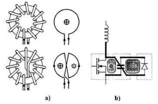
5. Use the principle of loop cancellation as much as possible to route, и дальше уменьшать площадь/dt loops (similar to twisted pair, use the principle of loop cancellation to improve anti-interference ability and increase transmission distance).

6. уменьшение площади контура не только уменьшает радиацию, but also reduces the loop inductance, улучшить производительность цепи.
7. уменьшение площади цикла требует от нас разработки каждого пути возвращения.
8. When multiple панель PCB are connected through connectors, Необходимо также рассмотреть вопрос о том, чтобы довести район кольцевой дороги до, especially for large di/dt signals, высокочастотный или чувствительный сигнал. A signal wire corresponds to a ground wire, Две провода как можно ближе. В случае необходимости, twisted pair wires can be used to connect (the length of each twisted pair wire corresponds to an integer multiple of the noise half-wavelength). если вы открываете компьютерную оболочку, you can see that the USB interface from the motherboard to the front panel is connected with a twisted pair cable. можно заметить, что двухниточное соединение очень важно для защиты от помех и уменьшения радиации.
9. линия данных, try to arrange more ground wires in the cable, и равномерно распределить эти заземления по кабелю, which can effectively reduce the loop area.
10. Although some inter-board connection lines are low-frequency signals, because these low-frequency signals contain a lot of high-frequency noise (through conduction and radiation), it is easy to radiate these noises if they are not handled properly.
11. When wiring, прежде всего рассмотрим следы высокого тока и подверженности облучению.
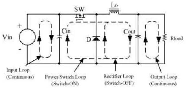
12. переключающее питание обычно имеет 4 контура тока: вход, выход, switch, по желанию. Among them, контур тока ввода и вывода почти постоянный, almost no emi is generated, но их легко беспокоить; Переключатели и контуры свободного тока имеют больше/dt, что требует внимания.
13. The gate drive circuit of the mos (igbt) tube usually also contains a large di/dt.
14. не помещать цепь малой сигнализации, such as control and analog circuits, внутренний ток, high frequency and high voltage circuits to avoid interference.
15. Reduce the susceptible (sensitive) signal loop area and trace length to reduce interference.
16. Small signal traces are far away from large dv/dt signal lines (such as the C pole or D pole of the switch tube, buffer (snubber) and clamp network) to reduce coupling, and ground (or power supply, in short, often Potential signal) to further reduce the coupling, and the ground should be in good contact with the ground plane. одновременно, small signal traces should be as far away as possible from large di/Dt - сигнальная линия. Do not trace the small signal under the large dv/dt signal. If the back of the small signal traces can be grounded (the same ground), связанные с ними шумовые сигналы также могут быть уменьшены.
17. лучше укладывать землю вокруг этих больших dv и сзади/Dt & di/dt signal traces (including the C/D poles of the switching devices and the switch tube heat sink), and use the upper and lower layers for grounding. соединение через отверстие, and connect this ground to a common ground point (usually the E/S - полюс переключателя, or sampling resistor) with a low-impedance trace. Это может уменьшить радиацию EMI. It should be noted that the small signal ground must not be connected to this shielding ground, Иначе это приведет к еще большим помехам.. Large dv/Dt - сопровождение обычно помехой при взаимодействии конденсаторов на радиатор и на прилегающую землю. соединять радиатор с экранированным заземлением. использование поверхностного коммутационного оборудования также уменьшит взаимную емкость, thereby reducing coupling.
18. Do not use vias for traces that are prone to interference, Потому что это может повлиять на все слои, через которые проходит дыра.
19. Shielding can reduce radiated EMI, но увеличение емкости от земли, conducted EMI (common mode, or extrinsic differential mode) will increase, Но если экран правильно заземляется, it will not increase much . взвешивать и учитывать в настоящем проекте.
20. защита от сопротивлений, use one point grounding and power supply from one point.

21. Switching power supplies usually have three grounds: input power high current ground, заземление на большом токе выходной мощности, and small signal control ground. The ground connection method is shown in the following diagram:
22. время приземления, the nature of the ground should be judged first, Тогда нужно установить соединение. The ground for sampling and error amplification should usually be connected to the negative pole of the output capacitor. пробный сигнал обычно извлекается из положительного полюса выходного конденсатора. Common impedance interference. обычно IC управляет заземлением и заземление привода не выводится отдельно. сейчас, сопротивление провода к земле пробоотборного резистора должно быть как можно меньше, чтобы уменьшить интерференцию общего сопротивления и повысить точность отбора проб тока.
23 The output voltage sampling network is close to the error amplifier instead of the output. Это потому, что сигналы с низким сопротивлением менее подвержены помехам, чем сигналы с высоким сопротивлением. The sampling traces should be as close as possible to each other to reduce the noise picked up.
24. Pay attention to the layout of inductances to be far away and perpendicular to each other to reduce mutual inductance, особенно накопительная и фильтрующая индуктивность.
25. обратите внимание на размещение высокочастотных конденсаторов при их параллельном использовании с низкочастотными конденсаторами, and the high-frequency capacitors are close to the user.
26. Low-frequency interference is generally differential mode (below 1M), высокочастотные помехи обычно являются общими модами, связь через излучение.
27. входной вывод, it is easy to form EMI (common mode). Вы можете установить кольцо на входе рядом с питанием. If the EMI is reduced, Это показывает проблему. The solution to this problem is to reduce the coupling or reduce the EMI of the circuit. Если высокочастотный шум не фильтруется, то очистка и проводимость к входному проводу, EMI (differential mode) will also be formed. At this time, the magnetic ring cannot solve the problem. String two high-frequency inductors (symmetrical) where the input lead is close to the power supply. A decrease indicates that this problem exists. решить эту проблему можно, улучшив фильтрацию, or to reduce the generation of high-frequency noise by buffering, зажим и другой способ.
28. Measurement of differential mode and common mode current.
29. The EMI filter should be as close as possible to the incoming line, путь к входу должен быть как можно короче, чтобы свести к минимуму связь между каскадом EMI. The incoming line is shielded with the chassis ground (the method is as described above). The output EMI filter should be treated similarly. увеличить расстояние между входной линией и высоким dv/dt signal traces, Это следует учитывать в будущих планах панель PCB layout.