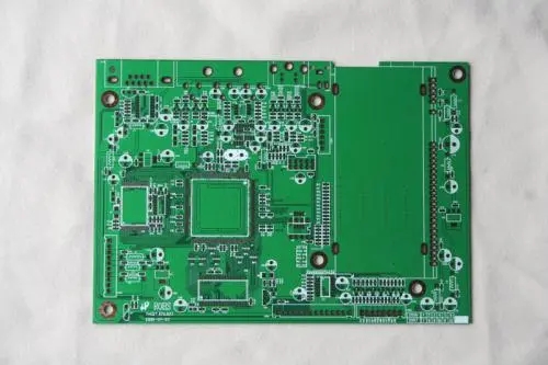
Briefly introduce you to the relevant knowledge of PCB schematics
In the research of PCB reverse technology, схема обратного выхода означает обратный запуск или прямое построение схемы PCB по чертежу файла PCB. It aims to explain the principle and working condition of the circuit board. схемная схема может использоваться для анализа собственной функции продукта. feature. в развитии прямого проектирования, general product research and development must first carry out schematic design, затем выполнить проектирование PCB according to the schematic. используется ли для обратного исследования принцип платы и эксплуатационные характеристики продукции, or is reused as the basis and basis of проектирование PCB в прямом проектировании, PCB schematics have a special role. поэтому, how to reverse the PCB schematic diagram based on the file diagram or the actual object, какие детали необходимо учитывать в процессе обратного вычисления?

1. Reasonable division of functional areas
Reasonable division of functional areas can help engineers reduce unnecessary troubles and improve drawing efficiency. Generally speaking, блок с одинаковыми функциями панель PCB are arranged in a concentrated manner, при обратном вращении карты по функциональным областям могут быть предоставлены удобные и точные основания. But the division of this functional area is not arbitrary. Он требует от инженера знания об электронных схемах. First, поиск основного компонента в функциональном модуле, в зависимости от подключения, you can find other components of the same functional unit to form a functional partition. формирование функциональных разделов является основой для построения схем. In addition, в процессе, don't forget to use the serial numbers of the components on the circuit board cleverly, Они могут помочь вам быстрее разделить функции.
2. Find the right reference parts
After determining the reference parts, drawing according to the pins of these reference parts can ensure the accuracy of the schematic diagram to a greater extent. инженер, the determination of reference parts is not very complicated. в нормальных условиях, the components that play a major role in the circuit can be selected as reference parts. обычно они размером больше, иглы больше, удобный для рисования. Such as integrated circuits, Трансформер, transistors, сорт., can all be used as suitable reference components.
3. Correctly distinguish lines and draw wiring reasonably
For the distinction between ground wires, линия питания, and signal wires, Инженеры должны также иметь знания о питании, circuit connection knowledge, знания PCB, and so on. различия между этими линиями могут быть проанализированы по соединению компонентов, the width of the copper foil of the line, и особенности самой электронной продукции. In the wiring drawing, чтобы избежать перекрещивания и вставки линий, a large number of grounding symbols can be used for the grounding line. различные линии могут использовать различные цвета и различные линии, чтобы обеспечить их ясность и ясность. For various components, Специальные метки, or even Draw the unit circuits separately, В конце концов их соединить.